Create a cut ready DXF file from a photograph
In this blog I would like to discuss my method for creating cut ready DXF files for CNC cutting systems using existing design work, artwork and even photographs. Chances are that you are part of the majority of business owners and hobbyists that have purchased introductory level or even advanced CNC cutting systems to find out later that it can be very time consuming and difficult to create custom design work suitable for cutting on your CNC cutting system. I would like to start this blog by encouraging each and everyone of you. I can assure you that there are software programs and designing methods that are available and affordable that can drastically reduce the amount of time you will spend creating design work that is cut ready for your CNC cutting system.
Before we begin creating a cut ready DXF file for your CNC cutting system we need to locate good quality design work, artwork or photographs to design from. It is very important to take time to locate high resolution images of what you want to cut with your CNC cutting system. There are lots of resources for locating high resolution images and you can get quick results by utilizing online search engines. The Google and Yahoo search engines provide image searches that will aid you in locating images of what you are wanting to cut with your CNC cutting system. These search engines will give you the ability to define your image search based on image size or as well as other image attributes.
Once you create a high resolution image you will need to save it to either your computer or a usb flash drive so that you can find it later. There are a wide variety of file formats that will work for your design project. The best image file formats to work with are going to be .jpg, .bmp, .svg, .pdf and .png. When getting ready to create a cut ready DXF file for your CNC cutting system you will want to make sure you have a suitable CAD or CAM based program that will enable you to convert your image into a cut ready DXF file for your CNC cutting system. The very best programs for this job are traditional graphic design programs that have the capabilities of exporting DXF files and importing DXF files. The two best programs for creating a cut ready DXF file for your CNC cutting system are Adobe Illustrator and Corel Draw. I would also like to make mention of Inkscape because it has been used successfully for the creation of cut ready DXF files for CNC cutting systems as well. From my experience Adobe Illustrator and Corel Draw are the best software programs for this job. Once you have acquired either of these programs(30-60 day free demo’s are available) it will be very important to take the time necessary to understand the basic operation of the software and the tools within these programs. There are numerous resources online for users of both the Corel Draw and Adobe Illustrator software programs. You will want to learn the following about the program you decide to go with.
How to open or import an image into a new document

The above image shows how to open an image into Adobe Illustrator CS6
How to select and deselect opened or imported images.

The above image shows the direct select arrow in Adobe Illustrator CS6
The above image shows what the photograph looks like when it is selected using the direct select arrow tool from the Adobe Illustrator CS6 software (blue bounding box around selected item)
How to scale or resize opened or imported images to specific sizes

How to add appropriate sizing or line weight to the lines you draw

The above image shows how to edit the line weight in Adobe Illustrator CS6
How to fill closed path objects with color
The above image shows how we can edit the fill color of objects in Adobe Illustrator CS6
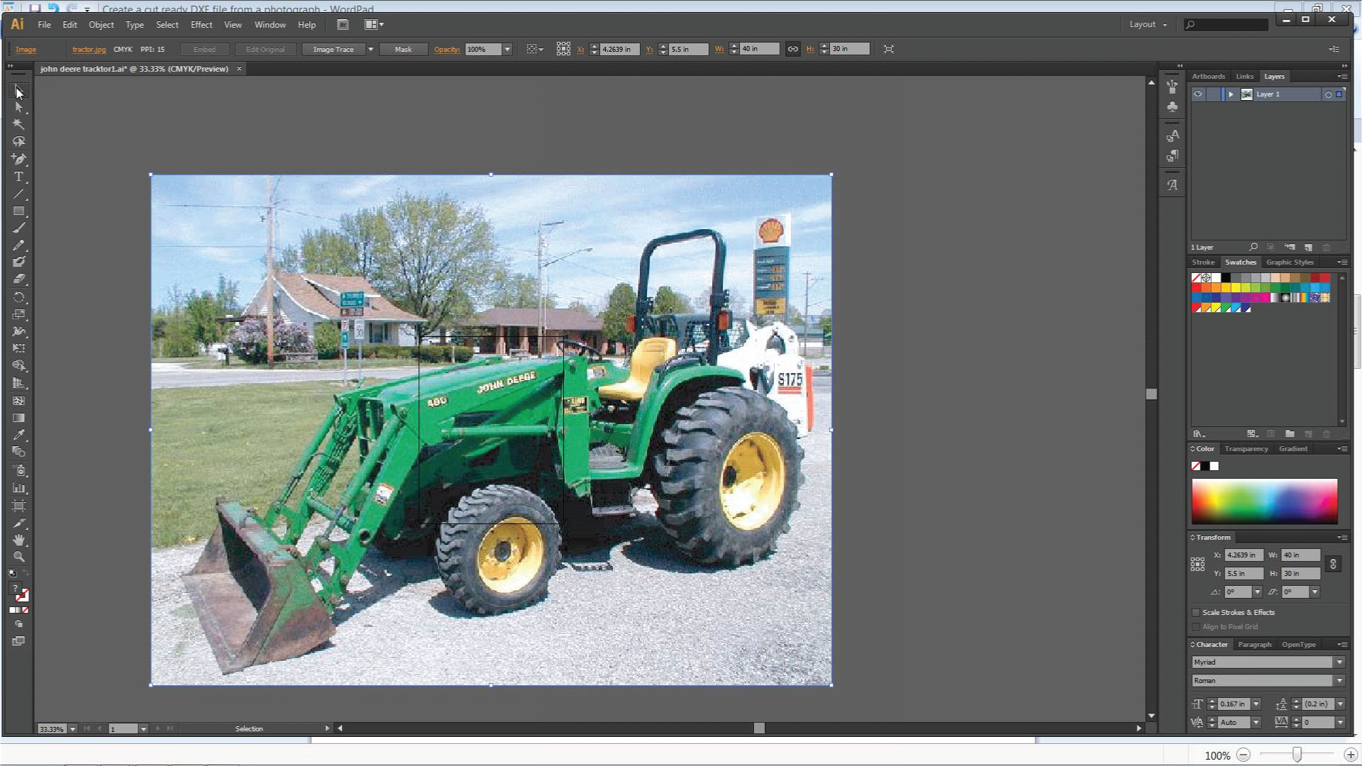
How to change opacity or transparancy of the opened or imported images.

The above image shows how to adjust the opacity/transparancy in Adobe Illustrator CS6
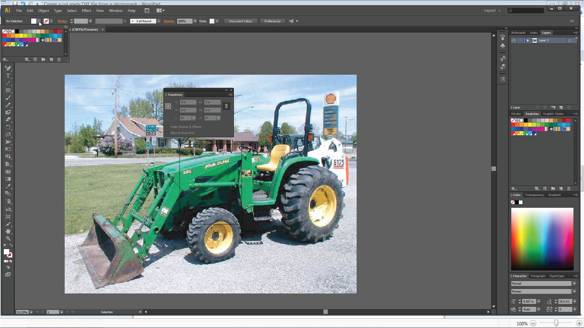
How to lock selected images into place.

The above image shows how to lock a selected item into place using Adobe Illustrator CS6
How to trace using a pen tool or pencil tool

The above image shows how to select the pen tool for tracing using Adobe Illustrator CS6
How to export DXF files from your document
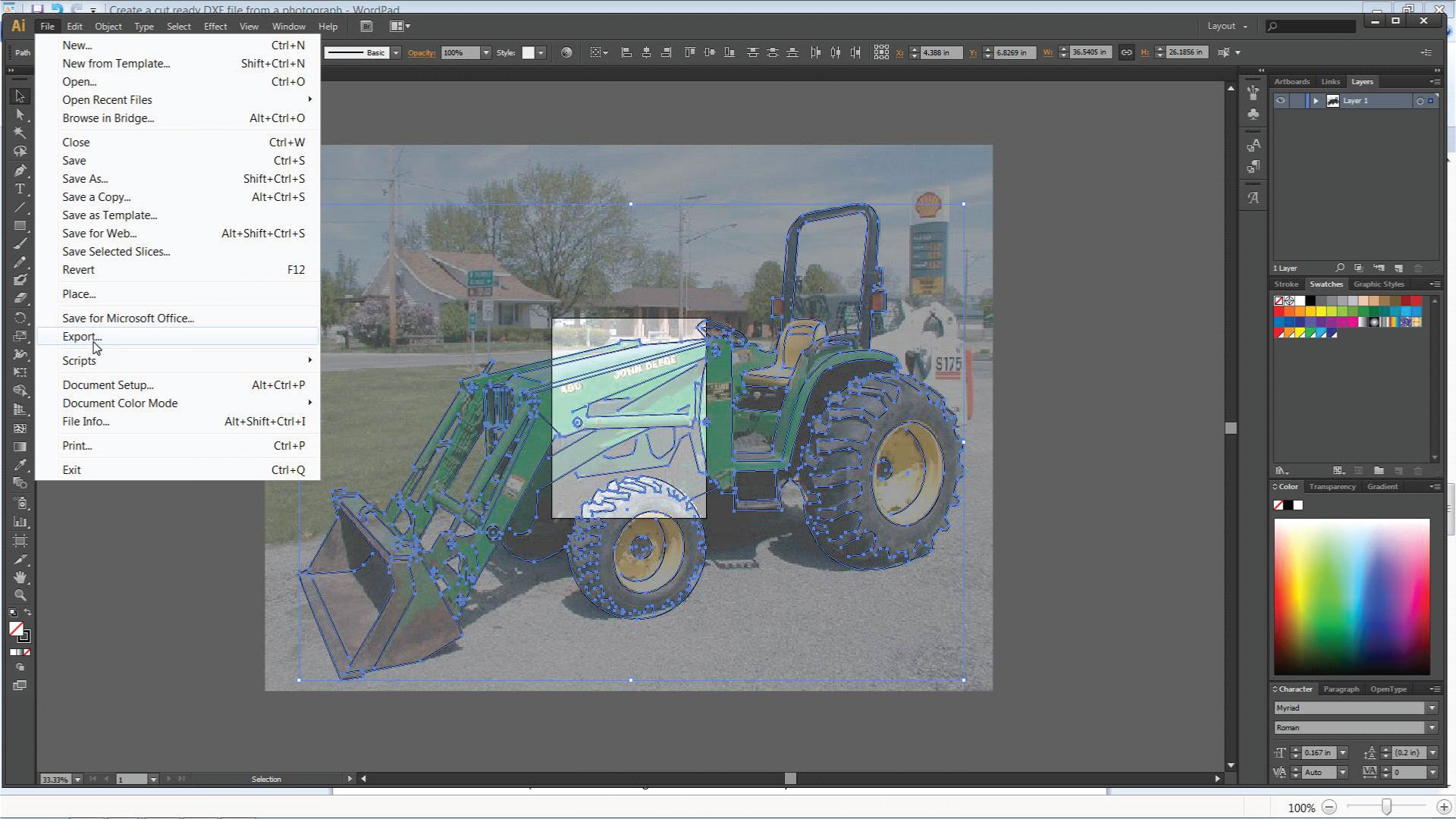
The above image is the first step in exporting a DXF file using Adobe Illustrator CS6

The above image is the second step in exporting a DXF file using Adobe Illustrator CS6

The above image is the third and final step in exporting a DXF file using Adobe Illustrator CS6
Start drawing!
Once you have learned these basics your are ready to begin creating a cut ready DXF file for your CNC cutting system.
The first step to creating a cut ready DXF file for your CNC cutting system is to open or import the image that you saved from the first step into your CAD or CAM based program.
The second step is to select the image and scale it to the size you want to cut it at.
The third step will be to change the opacity or transparency of your image. You will want to lighten the color of the main image so that you can see the tracing lines you will be creating later in this process. See the following image.
The fourth step is to lock the image into place so that it can not be selected or moved around accidentally.
The Fifth step begins by selecting an appropriate pen or pencil tool to begin tracing with. You will want to change the size of the line thickness/weight to .0625″ (represents the actual cut width of a Plasma cutting system set at 40 amps.
The sixth step will require you to trace the complete outermost silhouette of the image you want to cut out using the pen or pencil too. Then you can use a black fill color to represent the main silhouette and change the opacity so that you can still see the main image located below the silhouette that you just created. See the following images.

This is the artwork that I selected.

The main silhouette of the artwork has been traced in the above image

The main silhouette of the artwork has been traced in the above image and the fill color transparency has been lightened so that you can see the original artwork below.
The seventh step is to trace around the features that are within the main silhouette image that you want to have fall out during the cutting process. An example of this would be having the metal between the seat and the roll bar fall out. Also the metal between the hydraulic arms of the front loader on the tractor. Then you can use a white fill color to represents the pieces of the design work that you want to fall out during the cutting process. See the following image.

This is what the image will look like when you use a white fill color to represent the pieces of the design work that you want to fall out during the cutting process.
You can now focus on using a single line to highlight certain features that are found within the main silhouette of the image you are needing. I usually use a weighted line weight of .0625″ to represent my single line cut paths. See the following image.

The above image represents the single line cut paths as well as the cut paths that will result in pieces of the design work that will fall out (represented by the white fill color).
The final step is to remove all the fill color from the design work, select the cut paths and export/save the design work as a .dxf file.
The above image represents what your design work should look like before you try to export it as a .dxf file.

Once you have successfully exported your .DXF file you will want to import the resulting DXF file into a CAM based program to detect for broken lines or intersections.
